本文へスキップします。

ページタイトル

Band pass filter(soft coat)

ギャラリー

バンドパスフィルタ

Features

This is an interference filter that uses the interference of reflected light generated at the interface of a thin film. It can transmit a desired specific wavelength selectively.

Soft coatings deteriorate easily in environments of high temperature or high humidity. Depending on the environment of use and the application, we would suggest a hard coated band-pass filter with excellent durability.

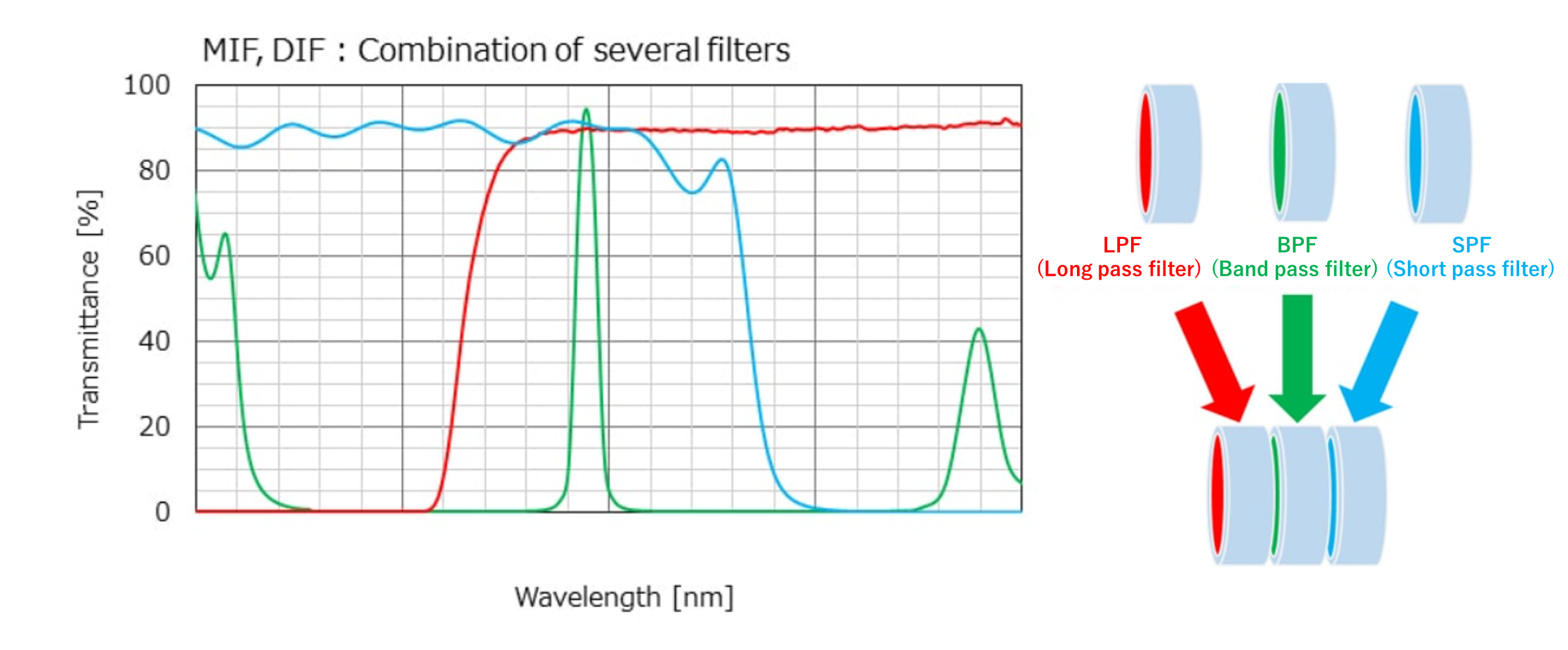
The company handles MIF (metal interference filters) and DIF (all-dielectric interference filters).
The standard characteristics are listed in the following table.

This filter consists of a combination of several filters as shown below to widen the inhibition band. In the case of soft coated band-pass filters, the LPF is usually colored glass. It is possible to inhibit ultraviolet to visible light with the absorption of colored glass.
For MIF and DIF, the inhibition band is set as standard, but it can be extended further. On the other hand, hard coated band-pass filters can be used with a single substrate.
 

MIF(metal interference filters)

This filter has a three-layer structure of semitransparent metal film, transparent dielectric film and semitransparent metal film formed on a glass or quartz plate with a glass or quartz plate bonded on top. When the optical interval of these two metal films is half or an integer multiple of a specific wavelength, the filter passes mostly light of that wavelength and blocks almost all light of other wavelengths. There are S and W types of metal interference filter depending on the degree of cut-off of the passed band.
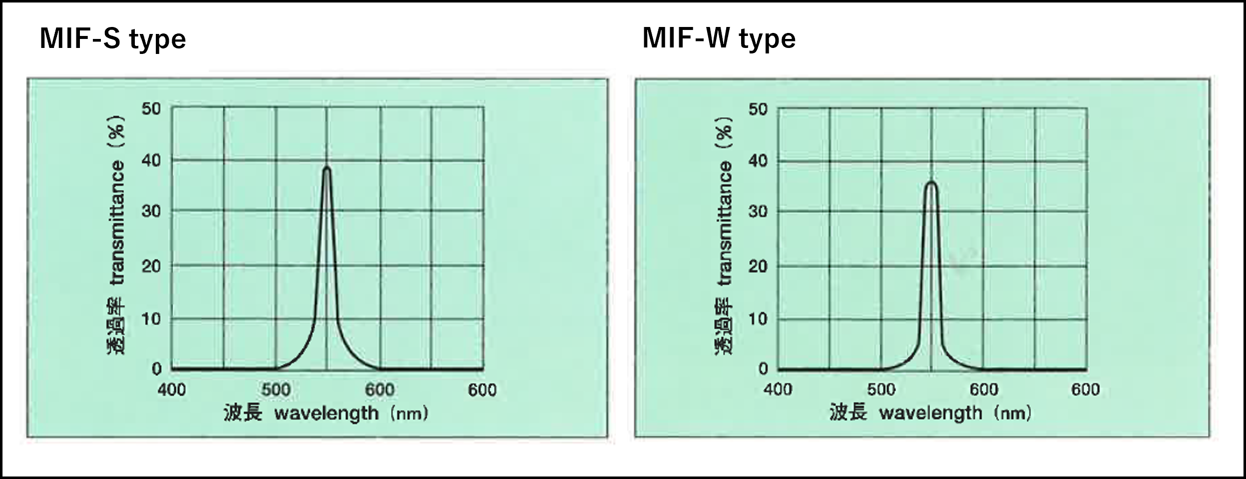


MIF-S type
Available wavelength range [nm] Maximum Transmittance[%] Half-width[nm] Center wavelength Tolerance [nm] Standard dimensions [mm]
Diameter Square
376-405 25-45 ≦18 ±3 15、20、
30、40、
50
50×50
406-475 30-45 ≦13 ±3
476-705 30-47 ≦13 ±3
706-955 30-45 ≦20 ±4
956-1195 28-45 ≦35 ±4
1196-1500 28-45 ≦40 ±5

Swipe the table below to scroll.

MIF-W type
Available wavelength range [nm] Maximum Transmittance [%] Half-width [nm] Center wavelength Tolerance [nm] Standard dimensions [mm]
Diameter Square
210-230 10-25 ≦20 ±3 15、20、
30、40、
50
50×50
231-260 15-25 ≦20 ±3
261-315 15-25 ≦25 ±3
316-375 15-25 ≦30 ±3
376-395 30-40 ≦25 ±3
396-455 35-48 ≦20 ±3
456-595 35-48 ≦15 ±3
596-700 35-48 ≦20 ±3

DIF(All-dielectric interference filter)

This is a filter that replaces the semi-transparent metal film of an MIF with dielectric multilayer film. Since dielectric multilayer film is highly transparent, transmittance increases so the wavelength of the transmitted light can be limited sharply. There are A, B and C type all-dielectric interference filters with a narrow half width and sharp transmission characteristics, and a BPF type with a wide half width.


Swipe the table below to scroll.

DIF-A/B/C type
Available wavelength range [nm] Standard cut region A type B type C type
Maxi-mum Trans-mittance [%] Appro-ximate ratio of half width to center wave-length [%] Maxi-mum Trans-mittance[%] Appro-ximate ratio of half width to center wave-length [%] Maxi-mum Trans-mittance [%] Appro-ximate ratio of half width to center wave-length [%]
420-429 Cut up to 720nm ≧35 0.70(3.0)
430-450 ≧40 0.70(3.1) ≧35 0.45(2.0) ≧35 0.25
451-499 ≧65 0.70(3.3) ≧50 0.45(2.1) ≧40 0.21
500-549 ≧70 0.75(3.9) ≧60 0.40(2.1) ≧40 0.20
550-599 ≧75 0.80(4.6) ≧65 0.40(2.3) ≧40 0.18
600-699 ≧75 0.85(5.5) ≧70 0.45(2.9) ≧40 0.16
700-799 Cut up to(Center wavelength/0.85) ≧75 0.90(6.8) ≧70 0.50(3.8)
800-899 ≧75 0.90(7.7) ≧70 0.50(4.3)
900-999 ≧75 0.90(8.6) ≧70 0.50(4.8)
1000-1099 ≧75 0.90(9.5) ≧70 0.50(5.3)
1100-1199 ≧75 0.90(10.0) ≧70 0.50(5.8)
1200-1299 ≧75 0.90(11.0) ≧70 0.50(6.3)
1300-1399 ≧75 0.90(12.0) ≧70 0.50(6.8)
1400-1499 ≧75 0.90(13.0) ≧70 0.50(7.3)
1500-1599 ≧75 0.90(14.0) ≧70 0.50(7.8)
1600-2000 ≧65 0.90 ≧60 0.50

Swipe the table below to scroll.

DIF-1/2/3/4/5 type
Available wavelength range [nm] Standard cut region BPF-1 type BPF-2 type BPF-3 type BPF-4 type BPF-5 type
Maxi-mum Trans-mittance [%] Appro-ximate ratio of half width to center wave-length [%] Maxi-mum Trans-mittance [%] Appro-ximate ratio of half width to center wave-length [%] Maxi-mum Trans-mittance [%] Appro-ximate ratio of half width to center wave-length [%] Maxi-mum Trans-mittance [%] Appro-ximate ratio of half width to center wave-length [%] Maxi-mum Trans-mittance [%] Appro-ximate ratio of half width to center wave-length [%]
430-450 Cut up to 720nm ≧55 1.20(5.3) ≧55 2.30(10) ≧60 3.80(17) ≧60 7.00(31) ≧65 13.0(57)
451-499 ≧60 1.30(6.2) ≧60 2.40(11) ≧65 4.20(20) ≧65 7.50(36) ≧70 14.0(67)
500-549 ≧70 1.50(7.9) ≧70 2.50(13) ≧70 4.50(24) ≧70 8.00(42) ≧70 15.0(79)
550-599 ≧70 1.60(9.2) ≧70 2.60(15) ≧70 4.70(27) ≧70 8.50(49) ≧70 15.5(89)
600-699 ≧70 1.70(11) ≧70 2.70(18) ≧75 4.70(31) ≧75 8.50(55) ≧75 16.5(107)
700-799 ≧75 1.70(13) ≧75 2.80(21) ≧75 4.80(36) ≧75 9.00(68) ≧75 16.5(124)
800-899 Cut up to(Center wave-length/0.85) ≧75 1.70(15) ≧75 2.90(25) ≧75 4.80(41) ≧75 9.00(77) ≧75 16.5(140)
900-999 ≧75 1.70(16) ≧75 2.90(28) ≧75 5.00(48) ≧75 9.00(86) ≧75 16.5(157)
1000-1099 ≧75 1.70(18) ≧75 3.00(32) ≧75 5.00(53) ≧75 9.00(95) ≧75 16.5(173)
1100-1199 ≧75 1.70(20) ≧75 3.00(35) ≧75 5.00(58) ≧75 9.20(106)
1200-1299 ≧75 1.70(21) ≧75 3.00(38) ≧75 5.30(66) ≧75 9.20(115)
1300-1399 ≧75 1.70(23) ≧75 3.00(41) ≧75 5.30(72) ≧75 9.50(128)
1400-1499 ≧75 1.70(25) ≧75 3.00(44) ≧75 5.30(77) ≧75 9.70(141)
1500-1599 ≧75 1.70(26) ≧75 3.00(47) ≧75 5.30(82) ≧75 9.70(150)
1600-2000 ≧65 1.70 ≧65 3.00 ≧65 5.30

Applications

Fluorescence analysis, Raman analysis, medical treatment, monochromators, lasers, optical communications, astronomy, etc.

Definition of central wavelength

The definition of the central wavelength (λ0) of a band-pass filter can be divided broadly into the two following types.
The type of soft coat band-pass filter differs depending on the product, so please use this as a reference. We design hard coated band-pass filters to meet customer requirements.

Type ①


Type ②